Luoyang Judian Metal Hot Processing Equipment Co., LTD is mainly engaged in the manufacture of complete sets of equipment in the metal thermal processing industry and the integration of the entire production line.
Home / Company News / Induction Hardening Furnace: Selection, Case Depth and Cost
Induction Hardening Furnace: Selection, Case Depth and Cost
2026.10.22
Induction Hardening Furnace: How to Specify the Right System
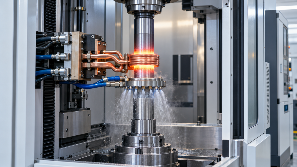
An induction hardening furnace heats selected areas of a metal component with an induction coil, then rapidly cools them to produce a hardened surface. It is commonly used for shafts, gears, axles, camshafts and other parts that need wear resistance in specific locations. The component remains solid throughout the process. Bodycote’s process overview
Although buyers often use the word furnace, the equipment is usually an induction hardening machine with a power supply, purpose-built coil, workholding, controlled movement and a quenching system.
Choosing that equipment starts with the part drawing. A power rating alone cannot tell you whether a machine will harden a gear root correctly, maintain a consistent case along a shaft or hold the required straightness after quenching.
How Induction Hardening Works
Alternating current flows through a copper induction coil, creating a magnetic field that induces electrical currents in the workpiece. These currents generate heat within the metal. For hardenable steels, the selected region is heated sufficiently to form austenite, then quenched to develop a hard martensitic structure.
The heating and cooling stages must work together. Reaching a displayed temperature does not, by itself, establish that the required hardened structure has formed. Heating rate, time at temperature and the material’s starting microstructure all influence the result. Inductoheat’s metallurgical guidance
Where the specification requires tempering, include it in the production plan from the outset. Tempering adjusts the hardness and toughness of previously hardened material; it may be performed in a separate furnace or an integrated induction station. ENRX’s induction applications guide
Define the Hardening Pattern Before Selecting Equipment
“Surface harden this shaft” leaves several decisions unresolved. The supplier needs to know which diameter requires treatment, where the hardened zone begins and ends, and how the hardness should change below the surface.
A useful enquiry includes the following information:
Requirement
What to Specify
Material
Exact grade, material condition and previous heat treatment
Hardened area
Marked drawing showing treated surfaces and excluded areas
Surface hardness
Required range, test method and measurement locations
Effective case depth
Depth range, defining hardness threshold and inspection locations
Core properties
Required core hardness or mechanical properties
Dimensional limits
Permitted runout, straightness and size change
Production demand
Part mix, batch size and required accepted parts per hour
Surface hardness and case depth describe different properties. A satisfactory surface reading does not show how far the hardened layer extends into the component.
For example, a drawing calling for a 2 mm effective case should also define the hardness threshold used to locate that boundary. The inspection plan should identify where the section is taken and whether the requirement applies before or after final grinding. Those details determine what the supplier must demonstrate during trials.
Select Frequency and Power Together
Frequency influences the distribution of induced current. Higher frequencies generally concentrate heating nearer the surface; lower frequencies allow deeper electrical penetration. The final hardened depth also depends on power density, heating time, material properties, heat conduction and quenching.
This is why a frequency-to-case-depth chart can only provide an initial direction. Electrical penetration depth and the measured depth of a hardened case are different quantities.
An unsuitable frequency can make the process harder to control. Excessive surface concentration may require longer heating to reach the specified depth, increasing the risk of surface overheating. Heating too deeply can enlarge the affected region and increase distortion. Inductoheat’s technical discussion of frequency and case depth
Power must then be matched to the area being heated and the available cycle time. Two systems with the same rated output can behave differently because of their coils, electrical matching and coupling to the workpiece.
Ask the supplier to explain the proposed frequency and power against your drawing. For a production machine, the proposal should also state the operating duty, expected heating time and allowance for the required throughput.
Check the Material and Its Incoming Condition
Induction hardening is widely used on medium-carbon and suitable alloy steels. Certain martensitic stainless steels and cast irons can also be treated, depending on the application. Bodycote’s materials overview
The material must be capable of developing the required hardness. Induction heating does not add carbon to the surface. A low-carbon steel therefore cannot be assumed to give the same response as a medium-carbon grade simply by increasing heating power.
Previous processing matters as well. Annealed, normalized, and quenched-and-tempered components can require different heating conditions even when their nominal steel grade is the same. Rapid induction heating makes these differences particularly relevant. Inductoheat’s guidance on starting microstructure
Send trial parts in the condition that the production machine will actually receive. A successful test on specially prepared material provides limited evidence for a different incoming condition.
Choose Between Single-Shot and Scan Hardening
In single-shot hardening, the coil heats the required region during one heating cycle, followed by quenching. This arrangement can suit compact components or defined features that can be covered by a dedicated coil.
In scan hardening, the workpiece and coil move relative to one another. A quench spray follows the heated region. This method is commonly used for shaft-type components and extended hardened surfaces. Ambrell’s explanation of the two methods
The choice affects tooling, motion control and production time. A long shaft may suit scanning, while a short, repeated feature may justify a dedicated single-shot arrangement. Gears require particular attention to whether the specified pattern covers the flanks, roots, tips or a combination of these areas.
For scanned parts, include the beginning and end of the hardened zone in the trial inspection. A section through the middle alone leaves those transition areas unexamined.
Treat the Coil and Quench System as Production Tooling
The induction coil determines where energy enters the workpiece. Its shape, position and relationship to the component influence the heating pattern. Coil manufacture, electrical matching and maintenance all contribute to performance. ENRX’s guidance on induction coils
Specify how replacement coils will be located and checked. A spare that fits mechanically still needs to reproduce the approved heating conditions. Changeover time, repair arrangements and replacement lead time deserve attention when the machine will support daily production.
The quench system needs the same level of scrutiny. Ask how the machine controls and monitors flow, temperature, timing and spray coverage. Where a polymer quenchant is used, concentration control belongs in the process specification.
Keep equipment cooling and workpiece quenching clearly identified in the proposal. They serve different purposes, and both affect reliable operation. Industrial monitoring systems commonly track electrical conditions and cooling-media variables to detect changes in the approved process. SMS Elotherm’s quality-monitoring overview
Compare Complete Systems When Reviewing Price
An induction hardening furnace quotation may cover a power supply and coil, or it may cover a complete production cell. Establish the scope before comparing prices.
Confirm whether the offer includes the hardening machine, fixtures, motion axes, quench unit, cooling equipment, controls, tooling and any required tempering stage. Then establish responsibility for installation, process development, training and acceptance testing. Complete systems are configured around workpiece dimensions, the hardness profile, automation and batch requirements. eldec’s equipment overview
Machine size is only part of the cost. A demanding hardness pattern, several part families, automatic handling or extensive traceability can change the project substantially.
Compare running costs on the basis of accepted parts. Include electricity, cooling, quenchant, coil maintenance, changeovers, inspection and any straightening or rework. A short heating cycle has less commercial value if loading or downstream inspection limits the line.
Set Acceptance Criteria Before Placing the Order
A demonstration showing a glowing component establishes that the equipment can heat it. Purchase acceptance needs evidence that the finished part meets the drawing.
Agree on representative trial material, inspection locations, surface hardness, effective case depth, hardened pattern, dimensional limits and any required crack or microstructure examinations. Specify whether results are evaluated after tempering and final finishing.
Also agree on the production demonstration: the part mix, run duration, loading arrangement and accepted output. Process records help establish repeatability, while sample testing verifies the metallurgical result. Real-time monitoring supports reproduction of an approved process; it does not replace that initial verification. SMS Elotherm’s explanation of monitoring and sample testing
For a useful equipment proposal, send the supplier a marked drawing, material specification, incoming heat-treatment condition and production target. Request a proposed coil arrangement, operating frequency, quench method, complete equipment scope and trial plan. That gives both sides a practical basis for deciding whether the induction hardening furnace can do the job.